The apply system (sometimes called the actuation system) exists in order to amplify the driver’s leg force and then convert it into hydraulic fluid pressure. In nearly all cases, the apply system functionality is not assigned to a single device. Instead, most apply systems accomplish this task by dividing the total responsibility among several discrete components.
While there are many different types of apply systems, most conventional vehicles use a combination of brake pedals, brake boosters, and master cylinders to get the job done. Variations on this recipe abound, but the fundamental objective remains the same: increase the applied force and turn it into pressure.
There is, however, one addendum. As you just learned in Chapter 4, brake pressure distribution between the front brakes and rear brakes can be used to optimize a vehicle’s brake balance. Consequently, the apply system may also contain additional devices which limit, regulate, or proportion the rear brake line pressure.
The pages that follow walk through these various components in detail, starting with the driver’s primary interface to the brake system: the brake pedal.

Most brake pedal pads are constructed from steel with textured molded rubber covers. The pedal shown here is actually made from cast aluminum for weight savings. Regardless of the aesthetic impact, the material of the pad itself doesn’t impact the brake pedal output. (Randall Shafer)
Brake Pedal Components
The brake pedal’s primary role is to mechanically increase the force exerted by the driver’s leg on the brake pedal pad. Remember, it’s essentially the amplified force from the driver’s leg that creates slip at the tire contact patches.
The brake pedal accomplishes this task as a direct result of its lever-based geometry. There are many different designs available, but all rely on the following series of individual components to get the job done.
Brake Pedal Pad
The brake pedal pad is simply where the driver provides mechanical force input to the brake system. Most OEM systems use a ribbed rubber pad molded over a steel or composite core, but exotic-looking brake pedal pads made from cast aluminum and/or with weight-saving holes are now becoming more commonplace. Regardless of its construction, the pad should be large enough that the driver will not miss the pedal in a panic, small enough that it won’t get hit by accident, and textured enough to prevent the foot from slipping off in the heat of battle.
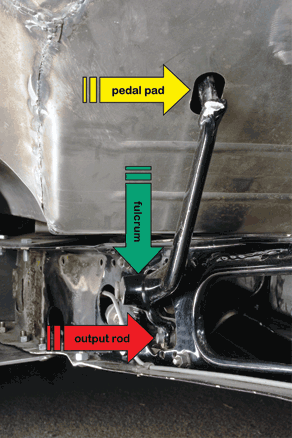
In most modern production vehicles, the brake pedal fulcrum is located at one end of the brake pedal arm. However, in many hot rod applications, the fulcrum (green arrow) is found between the brake pedal pad (yellow arrow, inside vehicle) and output rod (red arrow, under vehicle). In either case, the pedal ratio is calculated using the same equation. (Randall Shafer)
Fulcrum
The fulcrum is found on the opposite end of the brake pedal assembly from the brake pedal pad. This is the pivot point for the moving components of the brake pedal assembly. Usually it’s nothing more than a steel pin riding in a self-lubricating bronze bushing.
Output Rod
The output rod transmits the brake pedal output force from the brake pedal assembly to the next device in the brake system (typically a brake booster of some sort). Since it must swing through an arc as it travels, it’s usually located with a clevis bracket or, in racing applications, a spherical bearing, to allow for an angular misalignment between the two adjacent components.
Brake Pedal Arm
The brake pedal arm is the largest component in the brake pedal assembly. Its function is to locate the brake pedal pad at one end, the fulcrum at the opposite end, and the output rod somewhere in-between. In some racing applications the fulcrum is placed between the pad and the output rod, but the concept is still the same.
Due to the large leg forces a driver may be capable of applying, the brake pedal arm must be structurally sound to prevent deformation or collapse during severe use. For this reason, it’s usually designed to resemble an I-beam in cross-section with webbing often added for additional strength.
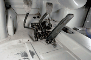
Ideally, the brake pedal arm should not bend or deflect during use. To make the arm as stiff as possible, it can be shaped like an I-beam or can be boxed along its entire length. This pedal simply uses extremely thick steel for its construction—crude, but effective. (Randall Shafer)
Brake Switch
The final component of the brake pedal assembly is the brake switch. This is the device used to illuminate the tail lamps of the vehicle when the brakes are applied. In most applications, it consists of a mechanical plunger on/off switch actuated by the brake pedal arm, but in some custom applications it’s common to have a pressure-actuated switch mounted in one of the master cylinder hydraulic lines.
There are many mechanical switches in use that allow you to adjust the plunger mechanism. In general, they should never be modified once they leave the factory. However, if you are changing other aspects of the apply system, it may be necessary to adjust the threaded mechanism to only illuminate the brake lamps when the driver applies the brakes.
After adjusting the brake switch, it’s a good idea to put the vehicle on jack stands and turn each of the road wheels by hand, since an over-adjusted brake switch can result in continuous brake drag. If the wheels are more difficult to rotate than before the adjustment, chances are the switch needs to be returned to its original position.
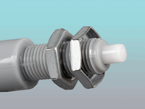
Although many brake switches employ a threaded mount for simple adjustment, this doesn’t mean that you should tamper with its setting. The adjustment feature is typically used for manufacturing flexibility at the vehicle assembly plant and not for tweaking later. (Randall Shafer)
OEM Brake Pedals
The brake pedal arm geometry (the location of the output rod relative to the brake pedal pad and the fulcrum) defines the pedal ratio. Note that this relationship holds true regardless of the location of the output rod relative to the fulcrum:
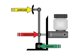
The brake pedal ratio is calculated by dividing the linear distance from the brake pedal pad to the fulcrum by the length from the output rod to the fulcrum. The larger the difference between the two distances, the more gain the brake pedal provides.
Pedal ratio (unitless) =
distance, pad to fulcrum (in) ÷
distance, output rod to fulcrum (in)
Typical brake pedal ratios (on conventional vehicles with vacuum boosters) are in the range of 3.5:1 to 4.5:1. Back in the days before booster assist became common, pedal ratios were more often in the range of 6.0:1 to 9.0:1. While these older designs certainly provided more mechanical advantage than most modern brake pedals, the corresponding increase in pedal travel made them undesirable.
As you learned back in Chapter 3, the primary design exercise becomes trading pedal ratio for pedal travel. In most street applications though, this is an academic point at best because modifying the brake pedal arm is a complex task best left to an experienced fabricator. This is not an area for novice experimentation.
Racing Brake Pedals
Despite the warning above, there may be times when modification of the brake pedal becomes necessary to offset a change elsewhere in the brake system. The most common need arises when a vacuum booster is removed from the brake system in a racing application. In this situation, the reduction in gain must be offset through a variety of different means starting with the brake pedal ratio.
Given the space and packaging limitations of a typical passenger vehicle, the maximum brake pedal ratio attainable is approximately 5.5:1 to 6.5:1. A brake pedal with a higher ratio usually won’t fit under the dash conveniently, at least if you are trying to modify the stock brake pedal arm to achieve this level of gain (which you probably shouldn’t be doing anyway).
Consequently, the best way to achieve a higher brake pedal ratio is to replace the OEM brake pedal with an aftermarket unit. Several makes and models exist, and should be selected based on your mounting needs (floor mount, firewall mount, or overhung), packaging constraints, and, of course, desired pedal ratio.
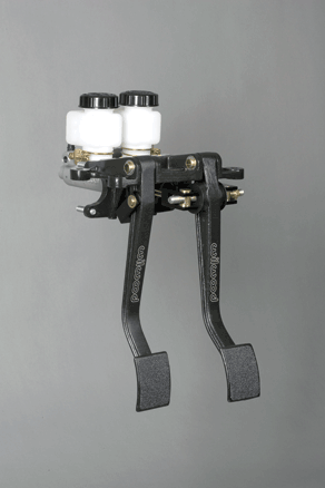
If you need more gain than the OEM brake pedal is capable of providing, invest in a racing brake pedal arrangement. Most, like the assembly shown here, aren’t designed to be used with vacuum boosters, so the master cylinders are mounted directly to the bracket. (Randall Shafer)
Brake Boosters
Although the details weren’t covered in Chapter 3, you’ve already learned that the brake booster is designed to further amplify the brake pedal output rod force. The ratio of input force to output force can be expressed as a linear gain as follows:
Booster output force (lb) =
brake pedal output force (lb)
x boost gain (unitless)
While there are a number of different designs in use, an overwhelming majority of vehicles use a vacuum-assisted booster. The rest either use a hydraulically assisted device to perform the booster function, or they simply go without.
