One of the most critical, yet least understood, brake system attributes is brake system balance. This single design parameter can make or break (no pun intended) a vehicle’s stopping distance performance. Even with the very best brake system components installed on your vehicle, improper brake system balance can prevent the tires from operating at their maximum decelerations simultaneously, resulting in vehicle deceleration performance that is far from optimized.
Improper brake system balance can also create undesirable vehicle dynamic responses. From a premature loss of vehicle steering during braking to dynamic instability while braking in a turn, the ramifications of improper balance can extend far beyond a few additional feet of stopping distance.
Unfortunately for the automotive enthusiast, screwing up a vehicle’s brake balance is pretty darn easy to do. Later in this chapter you’ll be presented with a table of those factors that can influence brake balance, but let it suffice to say that just about anything and everything brake related, suspension related, and tire related can have an effect (both positive and negative) on brake balance.
A vehicle with a balanced brake system creates brake forces at all four tires simultaneously that are equal to the maximum forces that each tire can sustain independently. You could also say that a balanced brake system is one that brings all four tires to their independent maximum coefficients of friction at the same time. In either case, defining perfect brake balance is quite a bit easier than designing a system that can pull it off.

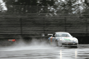
Even with the very best brake system components, improper brake balance can wreak havoc on vehicle braking dynamics. Stopping distance certainly can suffer as well. (Wayne Flynn/pdxsports.com)
Brake Force and Corner Weight

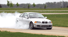
Tires generate brake forces through adhesive, deformation, and mechanical wearing modes of operation. Based on the surface, condition, and level of slip, a tire may be operating in one, two, or all three modes simultaneously. Tire smoke usually indicates too much mechanical wearing! (The Tire Rack)
In Chapter 2 you learned that the maximum brake force a particular tire can generate is equal to the coefficient of friction of the tire-road interface (mu in the equation below) multiplied by the amount of weight being supported by that corner of the car:
corner weight (lb) x mu (unitless)
To use real numbers, a single tire supporting 500 pounds of the total vehicle weight with a peak coefficient of friction of 0.9 (a typical value for an all-season tire on a dry asphalt road) could generate, in theory, a maximum of 450 pounds of braking force. Recall that this also would result in a maximum deceleration contribution of 0.9g at that one wheel.

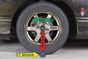
In this example, a single tire is supporting 750 pounds of vehicle weight (red arrow) with a peak coefficient of friction, or mu, of 1.1 (blue star). Therefore, this tire could generate, in theory, a maximum of 825 pounds of braking force (yellow arrow). The brake force would oppose the direction of travel (green arrow). (Randall Shafer)
Now if you were to place an additional 200 pounds on the same tire (700 pounds total), the maximum brake force rises to 630 pounds (this assumes that the peak coefficient of friction remains at 0.9). From this calculation you can see that an increase in maximum brake force does not result in higher deceleration (still 0.9g in this case). Why? Because the tire has more weight on it, and that additional weight requires its own additional force to decelerate.
Based on this relationship, you can also predict that reducing the weight on the tire reduces the maximum brake force sustainable by that corner. In the example above, if the weight were reduced to 300 pounds, a maximum of only 270 pounds of brake force would be available at that corner (again, assuming the same coefficient of friction).
Perfect Balance

In order to determine a vehicle’s static weight distribution, weigh the front and rear axles of the car. The percent front weight is the front axle weight divided by the total weight. The percent rear weight is the rear axle weight divided by the total weight. A nice set of scales will do the math for you, though. (Randall Shafer)
From all of these equations, ideal brake balance can be boiled down to one simple relationship. For perfect brake balance under all conditions:
Front brake force (lb) ÷
front vehicle weight (lb) =
rear brake force (lb) ÷
rear vehicle weight (lb)
Therefore, one could surmise that in order to design a perfectly balanced brake system you would just:
1. Weigh the front axle and rear axle of the car.
2. Design the front axle and rear axle brake components to deliver brake forces in the same ratio as the front-to-rear weight distribution.
3. Pat yourself on the back for achieving perfect brake balance.
For example, a vehicle with equal (or 50/50) front-to-rear weight distribution would appear to require front and rear brakes that generate the same amount of brake force simultaneously. In other words, the front brakes would provide 50 percent of the total required brake force and the rear brakes would provide the other 50 percent of the total required brake force.
Looking at a different scenario, it would appear that a vehicle with 60/40 front-to-rear weight distribution would require front brakes that provide 60 percent of the total brake force while the rear brakes would contribute the remaining 40 percent of the total required brake force. Why? Because of the extra weight being supported by the nose of the car.
In mini-summary, a perfectly balanced brake system generates brake forces at the front and rear axles in exact proportion to the front and rear axle weights. Like most things in life though, calculating brake balance is not as simple as it may appear and designing a braking system to these static conditions would neglect the most important factor in the brake balance equation—the effect of weight transfer during braking.
Static Weight Distribution
Let’s assume you have a 2,500-pound vehicle with an unknown static weight distribution. If you are only concerned with the vehicle at rest, it’s easy to determine the weight on each wheel. You just need to find some corner weight scales and weigh it.
The sum of the front individual corner weights (left front + right front) is equal to the front axle weight, and the sum of the rear corner weights (left rear + right rear) is equal to the rear axle weight. For example, if the sum of the front individual corner weights is 1,250 pounds and if the sum of the rear individual corner weights is also equal to 1,250 pounds, then you could say that the vehicle has 50/50 weight distribution. That is, half of the vehicle’s weight (50 percent) is being supported by the front axle, and the other half of the vehicle’s weight (the remaining 50 percent) is being supported by the rear axle.
The total weight of the vehicle is equal to the sum of the two axle weights (our original 2,500 pounds), and this weight can be thought of as acting through (or existing at) the vehicle’s center of gravity, or CG. Simple, right?

Either at rest or while coasting, every vehicle has a static weight distribution. Due to its rear-engine layout, this Porsche 911 has approximately 38 percent of its weight on the front axle and 62 percent of its weight on the rear axle prior to braking. (Daniel Mainzer)
Real-Life Brake Balance Success Story
How big of an impact can brake balance have on vehicle performance? It varies by application, but even with the very best brake system components, super sticky tires, and impeccable installation, skewing your brake balance can lengthen stopping distances dramatically. So much for those fancy red calipers…
To illustrate this point, here is a real-life brake balance success story reproduced with permission from Grassroots Motorsports during their Porsche 914-4 restoration.
“Our initial stopping distance measurements were not quite world-class. Even though we had installed Yokohama AVS Intermediate 195/60ZR15s at all four corners, we were recording stopping distances of 150 to 160 feet from 60 mph. There was obviously room for improvement.
“We then began to slowly adjust the proportioning valve until we were just barely on the verge of rear lock-up. We dialed back a tiny bit for a safety factor and again ran our stopping distance tests. Note that if you are doing this at home, you should be prepared just in case you go a bit too far and need to deal with the back end of the car getting all out of shape. A large parking lot or airstrip (as opposed to a crowded four-lane highway) is really the best place for this sort of thing.
“As stated earlier, the adjustable proportioning valve is a must-have item for anyone performing a 914-4 caliper swap. Our new stopping distance from 60 mph was now a scant 121 feet—on par with many of today’s premier sports cars. Apparently the brake bias was significantly holding us back from optimizing our new components.”
In this particular application, the stopping distance from 60 mph was reduced by approximately 34 feet—a whopping 22 percent! If you consider that out-braking your opponent by just two feet every lap for a twenty lap sprint race can result in a three to four car-length advantage at the checkered flag, a 22-percent decrease in stopping distance in every braking zone is sure to get everyone’s attention.

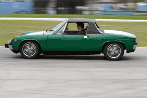
Paying attention to brake balance can pay huge dividends at the track. The 60 mph stopping distance of the Porsche 914-4 shown here went from 160 feet to 121 feet simply by setting the brake proportioning valve to an optimum position. (David S. Wallens/Classic Motorsports)